Coming Monday on The CircuitPython Show: Hear about the new audio effects in #CircuitPython and @todbot's quest for a fatter synth sound:
Recent searches
Search options
#circuitpython
Forbidden Planet “Krell” Display – MIDI CC Controller – Part 2
This revisits my Forbidden Planet “Krell” Display – MIDI CC Controller using my Forbidden Planet “Krell” Display PCB with a Waveshare RP2040 to create more of a “all in one” device.
Warning! I strongly recommend using old or second hand equipment for your experiments. I am not responsible for any damage to expensive instruments!
If you are new to Arduino, see the Getting Started pages.
Parts list
- Updated Forbidden Planet “Krell” Display (see below).
- Completed Forbidden Planet “Krell” Display PCB Build
- Waveshare Zero format device (I’m using an RP2040)
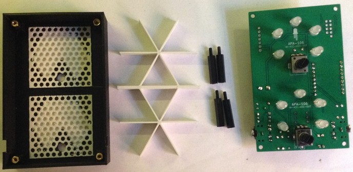
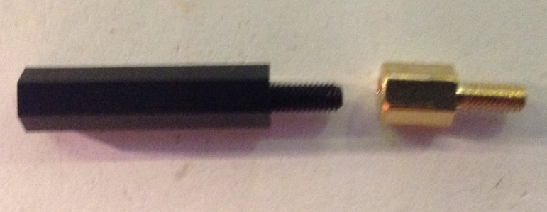
- 4x 6mm brass spacers
- 4x 20mm nylon spacers
PCB
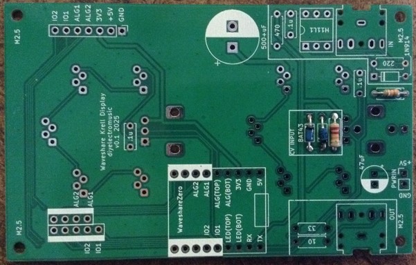
This requires a built of the Forbidden Planet “Krell” Display PCB with the following:
- 2 potentiometers
- MIDI IN and OUT
I’ve used potentiometers that are their own knob, as they only poke through the casing by around 5mm or so.
If it you are able to get longer shaft pots, then that would probably be worthwhile.
Updated 3D Printed Case
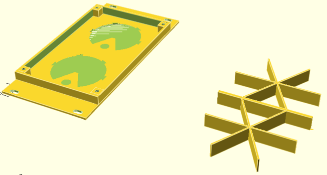
This requires the following from the Krell Display 3D Printed Case:
- 1x Frame
- 2x Inserts (with potentiometer holes)
- 1x EuroRack support
This requires the following options in the OpenSCAD code:
show_frame = 1;
show_quadframe = 0;
show_insert = 1;
show_support = 0;
show_quadsupport = 0;
show_eurorack = 0;
show_eurorack_support = 1;

alg_pot1 = 1;
alg_pot2 = 1;
alg_cv   = 0;
The frame does not really take into account the PCB at present, but I’ve reached the “good enough I want to do something else” stage, so I’ve just added a couple of small cut-outs (using a hacksaw) for the two MIDI sockets, and am content that the components stick out a bit from the back.
This cutout has to be 10.5mm from the end, 6mm wide, and 5mm deep.
At some point I might go back and design a deeper frame that has the cut-outs included and some kind of snap-on back to make it a self-contained box.
But for now, this is left as an exercise for, well, anyone else
Construction
I’ve used four brass 6mm spacers to screw into the mounting holes in the frame. Then the PCB can be inserted, taking care to squeeze in the 3D printed support around the LEDs and pots, and fixed with 20mm spacers which will also act as “legs”.
The Code
I’ve used a Waveshare Zero RP2040 and Circuitpython for this build. This is a combination of some of the test code used for the Forbidden Planet “Krell” Display PCB but with added MIDI.
The code supports both Serial and USB MIDI.
I wanted an equivalent of the Arduino map() and constrain() functions and didn’t immediate spot them in Circuitpython so wrote my own:
def algmap(val, minin, maxin, minout, maxout):
    if (val < minin):
        val = minin
    if (val > maxin):
        val = maxin
    return minout + (((val - minin) * (maxout - minout)) / (maxin - minin))
This allows me to map the analog read values (0 to 65535) down to MIDI CC values (0 to 127) whilst also allowing for some inaccuracies (I’ve treated anything below 256 as zero for example):
alg1cc = int(algmap(alg1_in.value,256,65530,0,127))
I’ve used the Adafruit MIDI library, which I’m still not really a fan of, but I wanted to include MIDI THRU functionality to allow the controller to sit inline with an existing MIDI stream. But it doesn’t seem to work very well.
I was already only updating the LEDs/MIDI CC if the pot values had changed, to cut down on the number of Neopixel writes required.
I experimented with changing the scheduling of the analog reads and MIDI but that didn’t seem to help very much. In the end I made sure that all MIDI messages queued up in the system would be read at the same time before going back to checking the pots.
    msg = midiuart.receive()
    while (msg is not None):
        if (not isinstance(msg, MIDIUnknownEvent)):
            midiuart.send(msg)
        msg = midiuart.receive()
It will do for now. Moving forward, I might try the Winterbloom SmolMIDI library. If that still doesn’t give me some useful performance then I might have to switch over to Arduino C.
Closing Thoughts
The MIDI throughput is disappointing, but then I’ve never really gotten on with the Adafruit MIDI library. I use it as USB MIDI on Circuitpython is so easy, so will need to do something about that.
I’m still deciding on the PCB-sized supports too. The original seemed to have nicer diffusion of the LEDs, but that could have been the difference between 5mm SMT neopixels and these THT APA106s which seem more directional in the first place.
And I really ought to finish the 3D printed case properly too.
So this is “that will do” for now, but I ought to come back and finish it off properly at some point.
Kevin
Forbidden Planet “Krell” Display EuroRack Module
This project uses my Forbidden Planet “Krell” Display and the Forbidden Planet “Krell” Display PCB Design but with some slight variations that means it could be EuroRack mounted with a control voltage (CV) input.
This is a DIY module only for use in my own DIY system.
Do NOT use this alongside expensive modules in an expensive rack. It is highly likely to cause problems with your power supply and could even damage your other modules.
https://makertube.net/w/qJqgTxxsEznTuF2DRVZT9o
Warning! I strongly recommend using old or second hand equipment for your experiments. I am not responsible for any damage to expensive instruments!
If you are new to microcontrollers, see the Getting Started pages.
Parts list
- 3D Printed EuroRack format Krell Display unit.
- Waveshare Zero format board – details here.
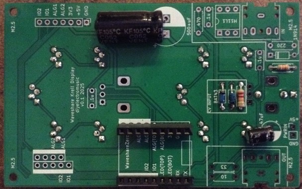
- Forbidden Planet “Krell” Display PCB built for EuroRack use (see below).
- Additional companion EuroRack power PCB (see below).
EuroRack 3D Print Design
This is an evolution of my original Forbidden Planet “Krell” Display box, but fitting into EuroRack dimensions: 128.5 x 60, which essentially makes it a 12 HP module.
It still takes the same inserts however, but now also includes options for holes for jack sockets or potentiometers:
show_eurorack = 1;
show_eurorack_support = 1;

alg_pot1 = 1;
alg_pot2 = 1;
alg_cv   = 0;
I’ve also included a special “supports” option for use with the PCB and the EuroRack case.
Krell Display PCB – EuroRack Build
To build one of my Forbidden Planet “Krell” Display PCB Designs for use with a EuroRack, follow the previous Build Guide but note the following differences:
- The MIDI circuits are not required when used as a CV input device.
- The lower potentiometer should be replaced with a CV input circuit.
- The upper potentiometer is optional, but I’m omitting it for my build.
- Power will come via the 5V jumper headers from an additional EuroRack power PCB (details below).
- Low-profile (e.g. 9mm high in total) headers should be used for the Waveshare Zero, but once again note the errata about the footprint on the PCB being too wide.
Here are some build photos of a build for EuroRack use. For this build there are only two diodes (the two BAT43) and two resistors (22K and 33K). Also note that none of the 100nF ceramic capacitors are required either.
Both electrolytic capacitors have been soldered into position on their sides as show below.
The Thonkiconn style mono jack shares the footprint are of the lower potentiometer on the LED side of the board, but be sure to get use the correct mounting holes as shown by the orientation below.
Nothing has been soldered to the power jumper yet. See the discussion below for how to link this to the power board.
Krell Display Companion EuroRack Power PCB
Bill of Materials:
- Waveshare Zero “Krell” Display EuroRack power PCB (Github Link below).
- L7805 TO-220 format regulator or equivalent (see discussion below).
- 1x 16-way DIP EuroRack shrouded header.
- 1x 1N5017 Zener diode.
- 2x 47uF electrolytic capacitors.
- 1x 100nF ceramic capacitor.
- 2-way Jumper header socket and pins (probably need extended pins – see discussion).
I’ve opted to use a DC-DC converter with a 7805 physical footprint as shown below.
If a 7805 regulator is used then a heatsink will almost certainly be required. I’ve oriented the regular to allow for a “tab up” mounting which hopefully leaves plenty of room for some kind of heatsink to be used.
Here are some build photos.
There is an option on the PCB to install a 10R resistor as is sometimes recommended for EuroRack modules. From what I’ve read this seems to be to allow it to act as a “fuse” in the case of an incorrectly wired module. As I’ve discussed before (see here) I’m not sure this is so relevant for me, so I’m using the provided solder bypass bridge to leave it out.
Note the orientation of the DC-DC converter.
I’ve used extended pin headers for the power link between the two boards, but due to an error in positioning, they’ve had to be bent over slightly – more on that later.
Physical Build
A completed unit has the following parts:
- 3D printed case, PCB supports, and two “krell” inserts.
- Main PCB built for EuroRack use as described above.
- Power PCB as described above.
- M2.5 spacers and fixings as follows:
- 4x 6mm M2.5 brass fixings.
- 4x 15mm M2.5 nylon fixings.
- 4x M2.5 nylon screws.
The power link between the two PCBs has to be trimmed and slightly bent as shown below.
Once the whole thing is put together, there isn’t room, at least on my build, for the nut to be put on the jack socket. Also, the 6mm and 15mm spacers might be slightly too short, depending on how far off the PCBs the LEDs ended up. Some experimentation and “encouragement” is probably required to get everything together.
The Code
The code is relatively straight forward, and is largely a mix of the analog and neopixel test code from the Forbidden Planet “Krell” Display PCB Build Guide.
One quirk is scaling the analog read from 0..65535 to a useful 0-10 to allow for zero to 10 leds to light up. I’ve allowed for a range of values to be “basically zero” too to allow for some jitter or noise.
As I only write out to the neopixels when something changes, this code seems to be quite responsive.
This requires the following Adafruit Circuitpython Library Bundle libraries:
- neopixel.mpy
- adafruit_pioasm.mpy
- adafruit_pixelbuf.mpy
In fact, the entire Circuitpython code is given below.
import time
import board
import neopixel
from analogio import AnalogIn

cv_in = AnalogIn(board.A3)

pixel_pin1 = board.GP2
pixel_pin2 = board.GP3
num_pixels = 5

pixels1 = neopixel.NeoPixel(pixel_pin1, num_pixels, brightness=0.3, auto_write=False, pixel_order=neopixel.RGB)
pixels2 = neopixel.NeoPixel(pixel_pin2, num_pixels, brightness=0.3, auto_write=False, pixel_order=neopixel.RGB)

col = (80, 35, 0)

lastcv = -1
while True:
    cv = cv_in.value / 256

    if (lastcv != cv):
        lastcv = cv
        led = cv / 25
        for pix in range(5):
            if (pix < led and cv > 5):
                pixels1[pix] = col
            else:
                pixels1[pix] = 0

            if (pix+5 < led and cv > 5):
                pixels2[pix] = col
            else:
                pixels2[pix] = 0

            pixels1.show()
            pixels2.show()
GiHub Resources
There is now an updated version of the OpenSCAD code for the case on GitHub and the PCB and code are also now available.
- OpenSCAD code and STL models: https://github.com/diyelectromusic/sdemp_3dprints/tree/main/KrellDisplay
- PCB: https://github.com/diyelectromusic/sdemp_pcbs/tree/main/WaveshareZeroKrellDisplay
- Code: https://github.com/diyelectromusic/sdemp/blob/main/src/SDEMP/CircuitPython/KrellEuroRackDisplay.py
Closing Thoughts
This isn’t a perfect build in mechanical terms, but I’m not sure I ever do anything perfectly anyway, especially where mechanical things are concerned, but the final result is pretty pleasing.
The video shows it running with a Pimoroni RP2040 in the driving seat. First a potentiometer provides a 0 to 5V input, then I’m using my Educational DIY Synth Thing‘s LFO to provide a 0 to 3V3 input.
Kevin
Coming Monday on the next episode of The CircuitPython Show: A panel discussion with @todbot, core developer @stylus, Mark Komus, and Cooper Dalrymple all about the new audio effects in #CircuitPython. Here's Cooper on what the effects are based on:
Do you or your business have a #YouTube channel? Want to create your own colorful LED display sign with scrolling address & subscriber / views stats? Change just one config file & this #CircuitPython project is ready to go! Learn how here: https://youtu.be/OV67IjXsQbA?si=atS-sDFxkyc3VSUd
I wrote about a project I did for my kid a few weeks ago: he found using a regular die for dice chess inconvenient, so I replaced it with an ESP32 and some Python code.
https://blog.dowhile0.org/2025/03/28/creating-an-esp32-based-dice-for-chess/
#CircuitPython controlled pocket operator. KB2040 is setup as a midi in device. Reason is sending out four midi tracks on four different midi channels. Each button/synth voice on the pocket operator is assigned a midi channel. When a note on message comes in on the corresponding channel, the button is triggered via GPIO through a mosfet. The DAC is controlling the pot that is used for notes for some of the synth voices #pocketoperator
And just like that we have a functioning clock! currently running on a propmaker RP2040 but I will probably have to move over to something WiFi enabled before long #pcb #electronics #maker #RP2040 #RaspberryPi #jlcpcb #circuitpython @adafruit
@rpimag I did a bit more work on my UART booting Flashless Picos. On the end of each "pico" there's an I2C port for the I/O expander (used to reset/setup the RP2350A to boot from UART) and a UART port to send the bin file/communicate after boot. The Pico2 in the PicoUART6 is running CircuitPython using Adafruit_CircuitPython_PIO_UART for the non-hardware UARTs.
Couldn’t get button 6 to work consistently but otherwise 15/16 synth sounds are controllable from the KB2040. Quick test sketch in #circuitpython toggling the GPIO and cat LED (slow cycle RGB led)
Work in progress of a Reverb sound effect for CircuitPython. Based on FreeVerb. #CircuitPython #Reverb
Love getting the Instructables email from AutoDesk and seeing a student’s #CircuitPython project highlighted. Nice work on Tilt-a-Sketch, Alfonso DeVito ! https://www.instructables.com/Tilt-a-Sketch/
#CircuitPython 9.2.6 released!
https://blog.adafruit.com/2025/03/22/circuitpython-9-2-6-released/
Highlights of this release
- Fix `storage.remount("/", readonly=False)` regression.
- Fix RP2xxx WiFi mDNS limitations.
NeoPixel LEDs are cool. Making them twirl up & down a light strip by using a potentiometer? Even cooler. And doing it with python slices using a @RaspberryPi Pico? Super fun! Dig in to the latest lesson of #CircuitPython School. #CSEd friends, STEM goodness for your class https://youtu.be/1-sgErNV-b0?si=jeHuiRYTzMKbF4Q9
#CircuitPython 9.2.5 released!
Highlights of this release:
- Update frozen modules.
- Enable function attributes and reverse arithmetic operators on most boards.
- displayio:
- Add tilepalettemapper.
- Add VT100 escape code support for scrolling and colors.
- synthio and audiodelays additions.
- Add audioio on Espressif.
- Add spitarget on SAMx (enabled on most SAMx5x boards).
- Initial work on a Zephyr port.
- Bug fixes.
https://blog.adafruit.com/2025/03/18/circuitpython-9-2-5-released/
Would-be DJs, #Makers, and #STEMEd friends, learn how to mix-sounds & on a low-cost touch-reactive board! This super-fun #CircuitPython lesson is one my students love. @RaspberryPi Pico & @Adafruit CircuitPlayground Bluefruit code/wiring shown. 32-bit Word to your Mother. youtu.be/RkrbChO-jGk
Hackers are in love with new low-cost, long range "LoRa" radios. In this NullByte episode, Davis DeWitt shows how LoRa can control anything remotely, even in the noisiest of radio environments (DTLA).
Check out the real-world test, and the #CircuitPython example code to try it yourself!
#Makers have you ever wanted to control LED lights from an app? Learn how using sample #CircuitPython code, an @Adafruit CircuitPlayground Bluefruit, and the free Bluefruit Connect app. Here's the lesson I give all of my students. https://youtu.be/AwD3sar--BY?si=rgvoWR4qpMNIkBiO
New episode of The CircuitPython Show! @todbot
and @cedargrove stop by and share their experiences writing drivers and libraries for The #CircuitPython Community Bundle and share some of their favorite libraries.
Find the show wherever you get your podcasts or visit https://www.circuitpythonshow.com/@circuitpythonshow/episodes/writing-a-circuitpython-library-for-the-community-bundle


